The Max-Prop propeller should be greased on a regular basis (maybe once year). At times it also worth taking it off the shaft and clean it more thoroughly. Ours is an older (2003) Max-Prop VP 3 blade 21-inch propeller. Instructions/manual can be found at PYI Inc. | Max-Prop Automatic Feathering Propellers.
Rotation direction
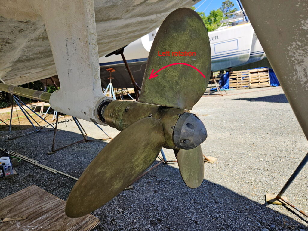
On our sailboat, the rotation of the shaft is left/counterclockwise when propelling the boat forward. As a convention the direction of the rotation is to be taken as looking forward from aft.
Adjusting the pitch
On our boat the pitch should be set at 14.5 which corresponds to a blade angle of 20 degrees according to the instructions manual. Proper pitch can be theoretically determined from the engine and transmission characteristics as well as hull speed. We still had to adjust after sea trials. Initially the pitch was set too high (blade angle 22 degrees) and the motor was smoking black smoke with the boat unable to come up to its hull speed. Mike at Bock Marine (a very experienced navy mechanic) was able to diagnose the issue immediately.
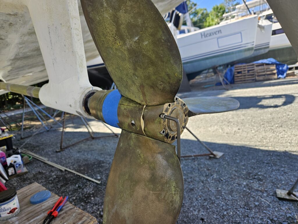
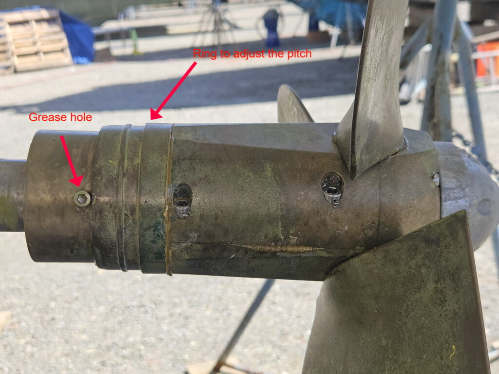
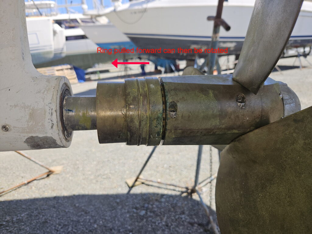
On the hub, there is an adjustment ring with engraved markings for various blade angles on left and right rotation. To adjust the blade angle, one must pull the ring forward and then rotate to the desired position. On the photo one cannot see the engraved marks very well due to the Propspeed paint. So we had to do our own mark.
Greasing
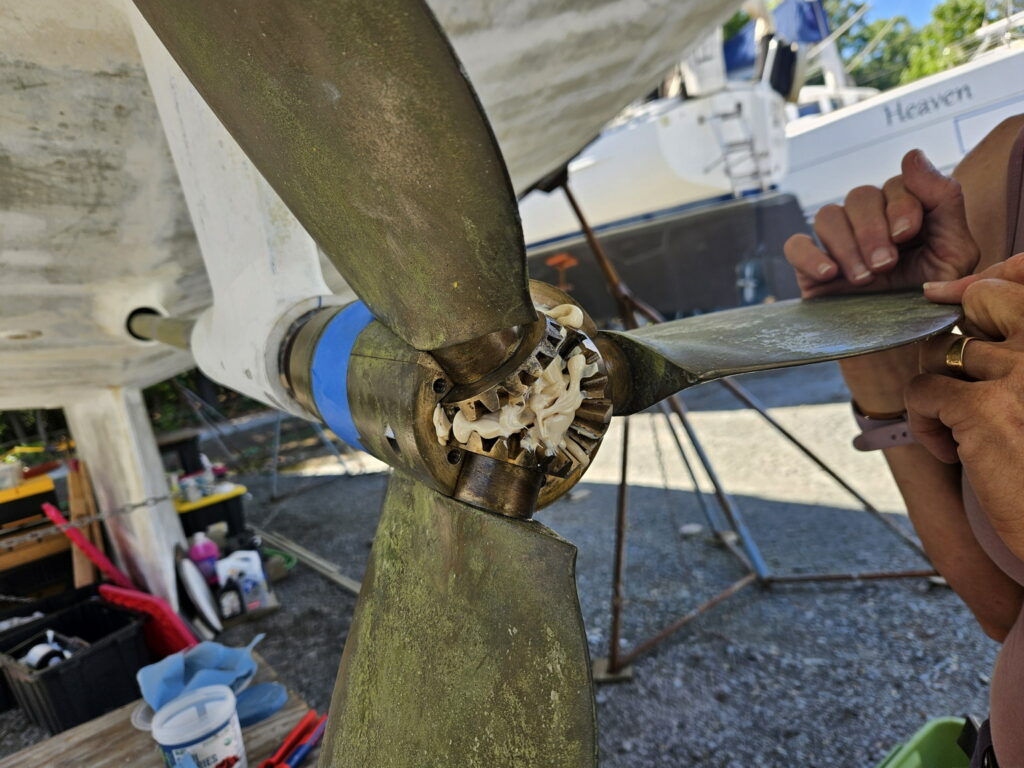
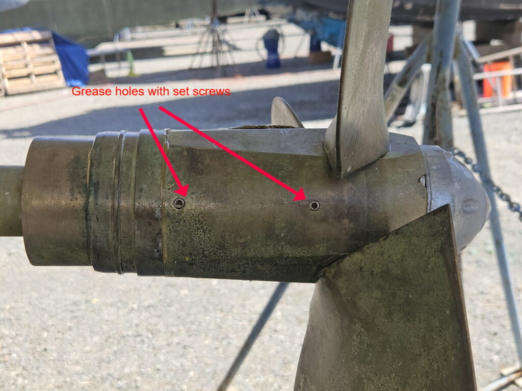
There are three holes to inject new grease (Lubraplate “130 AA”). The forward hole is on the hub forward; the two others are on the spinner. The new grease will expel the old/dirty one through various joints between the blades, the spinner and the hub, etc… From the manual, it looks like one can do one hole at a time, from forward to aft. We inject new grease until the grease that comes out looks new (white, as opposed to dirty/black old grease).
Disassembling and cleaning
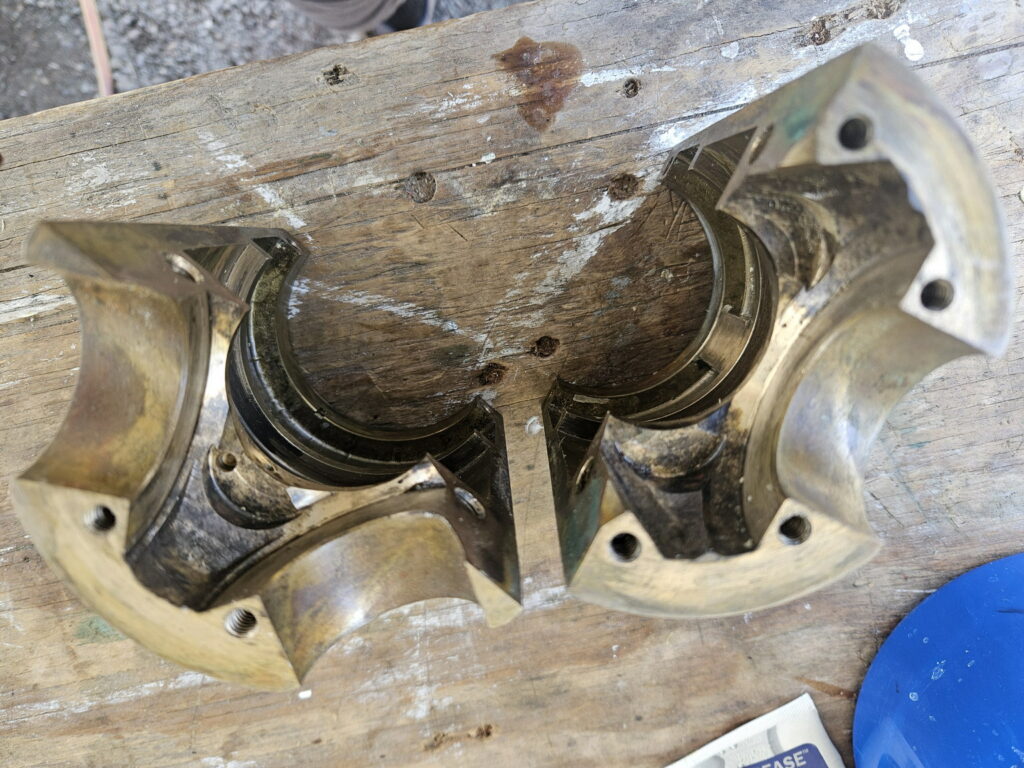
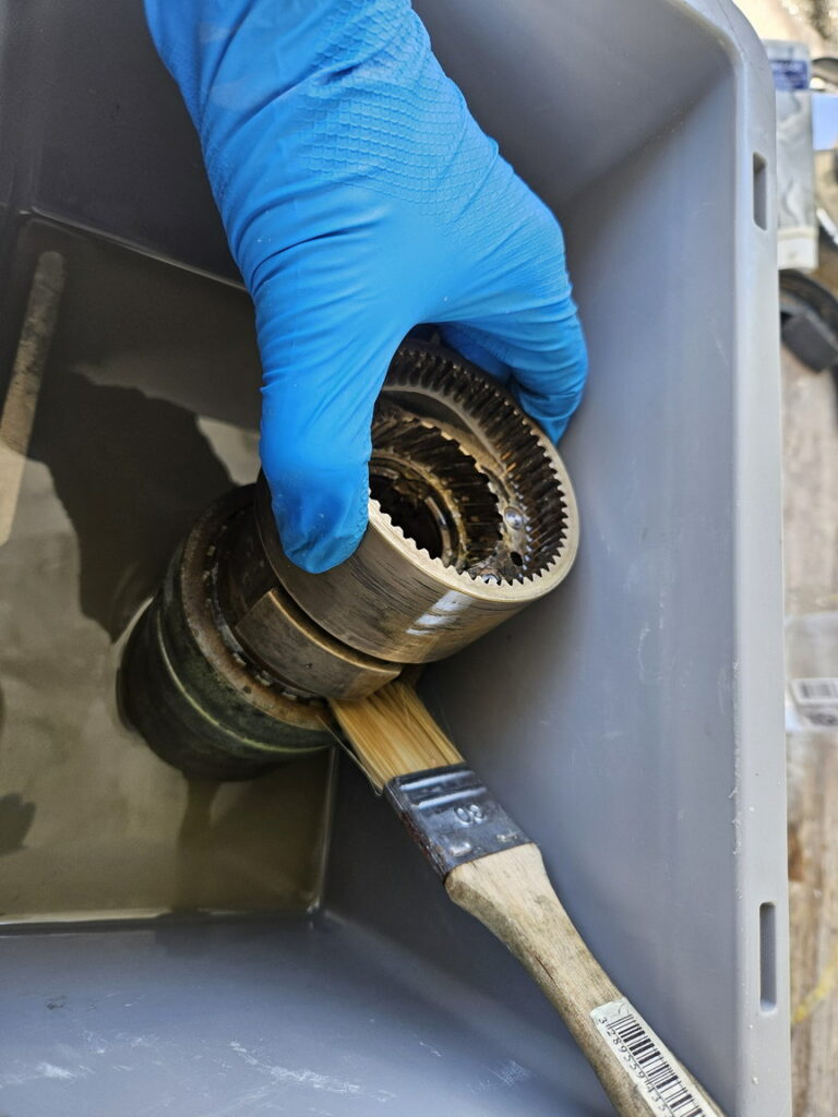
When greasing, there was no old grease coming out aft the propeller. I decided to take it apart to see why. In doing so, I found a lot of dirt/soil, especially at the aft end. I used white spirit to soak and clean the parts with a paint brush.
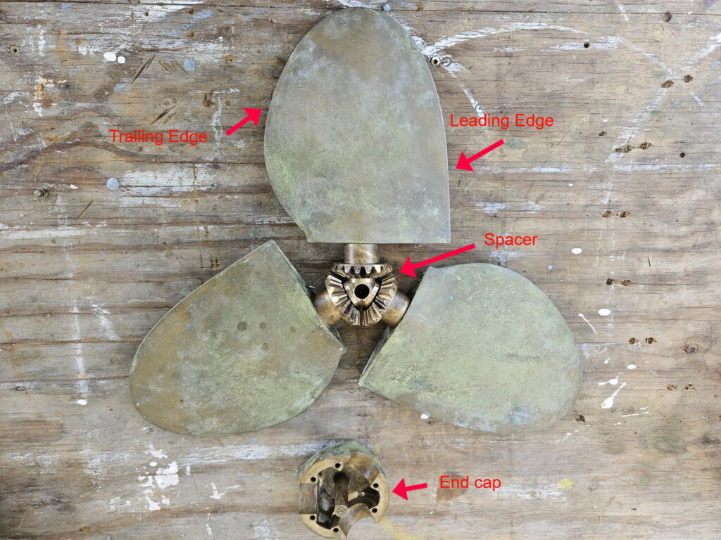
To disassemble the propeller, start taking off the end cap; then pull out the three blades along with the spacer.
Then dismount the two parts of the spinner. That is straightforward.
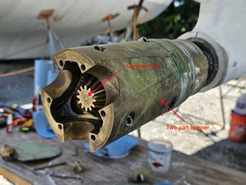
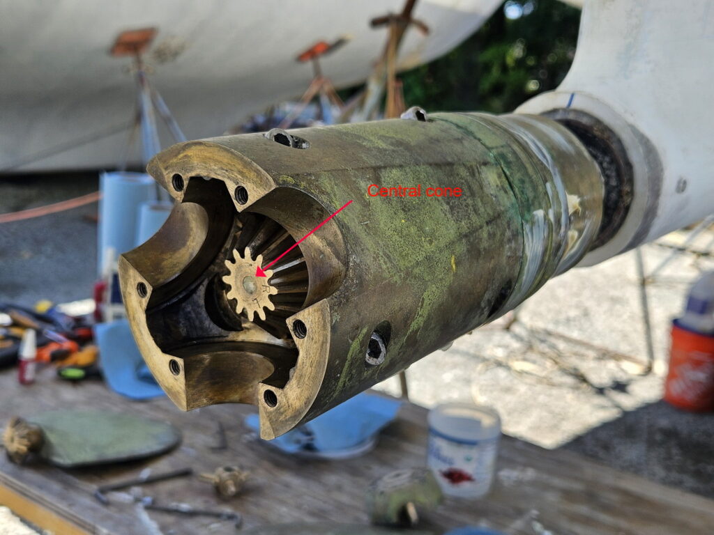
One can then pull out the central cone gear. It is not locked, and if tight (ours was a little bit
stuck with dirt), one can delicately use pliers making sure not to mark the metal.
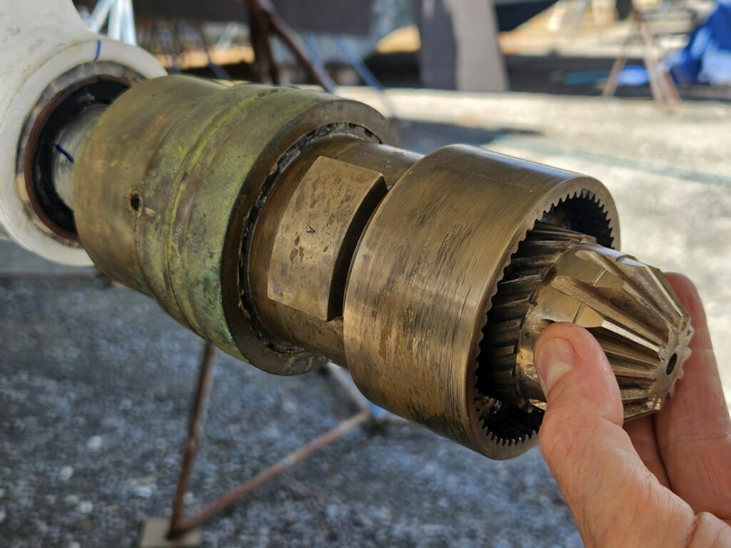
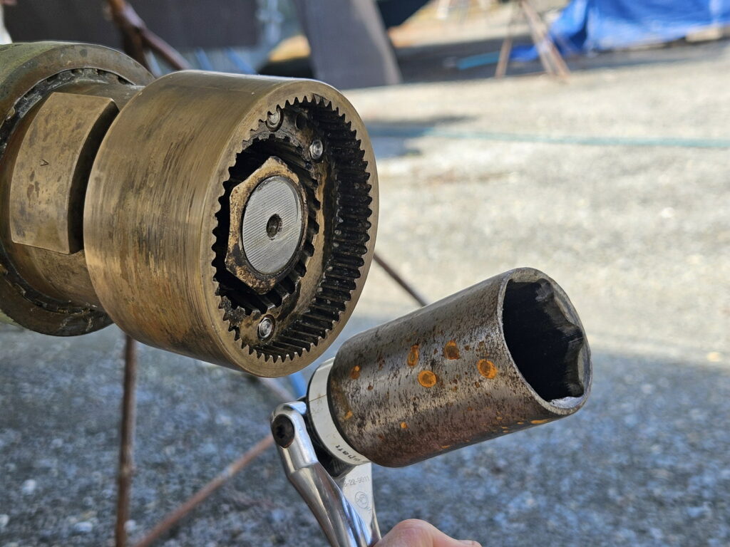
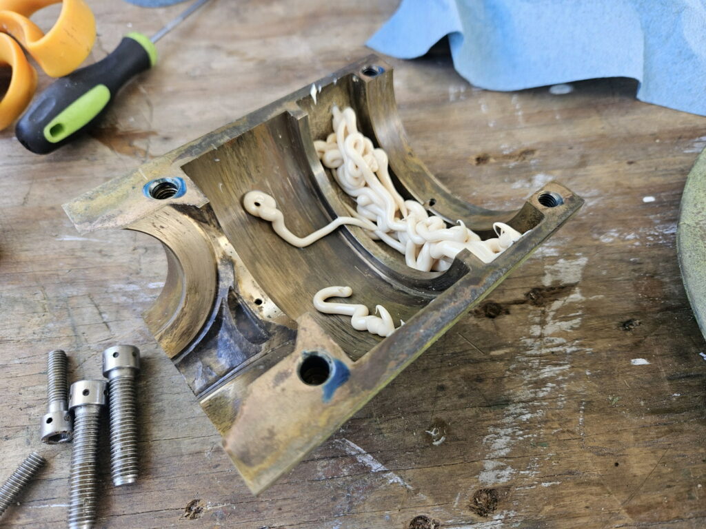
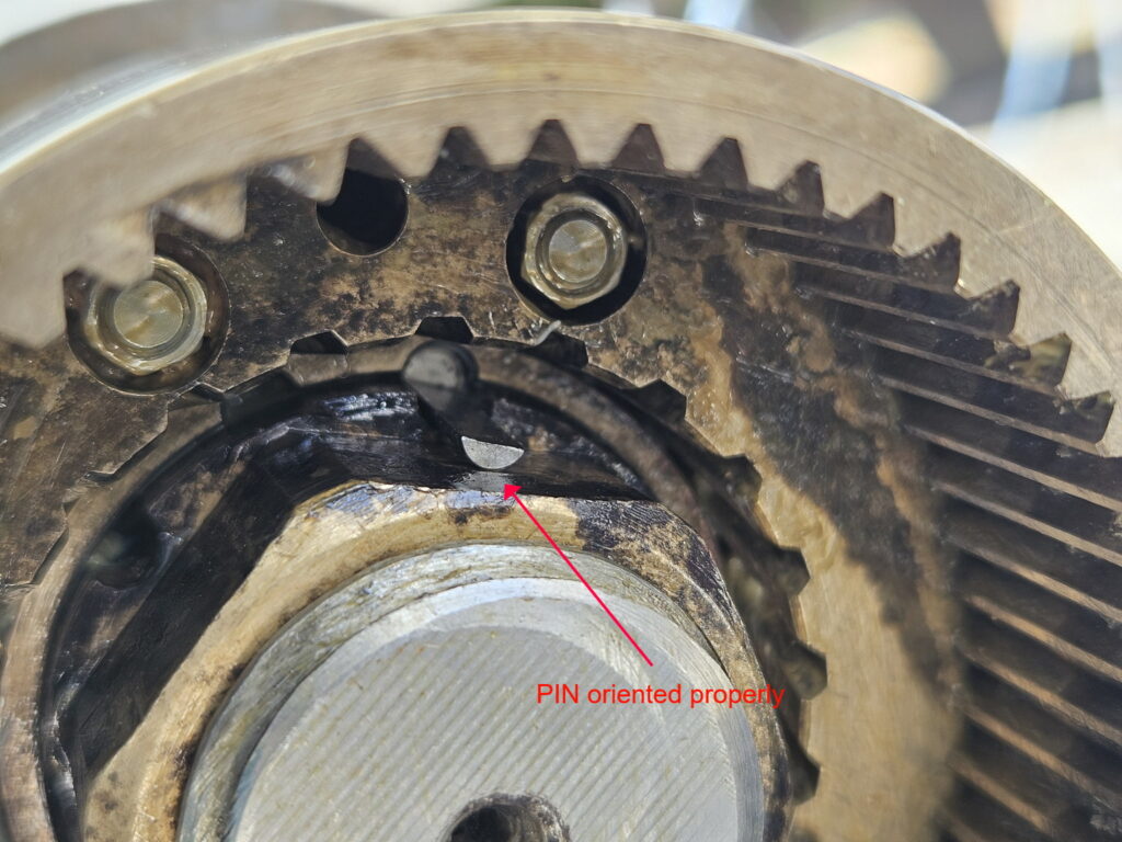
Next step is to unscrew the central nut on the shaft. The nut is locked in place by two locking pins to prevent it from rotating and coming lose with vibration. I removed those two pins pulling them with needle nose pliers. The central nut unscrews like a regular screw, that is counterclockwise/left rotation to unscrew.
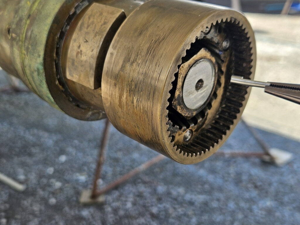
We use a modified 34mm socket with long handle to have leverage. We had to grind the walls of the socket, so it is thin enough to be inserted onto the nut. The difficulty here is to lock the shaft and prevent it from turning. What I did is engage the transmission in reverse. That held the shaft from rotating sufficiently for the nut to come loose.
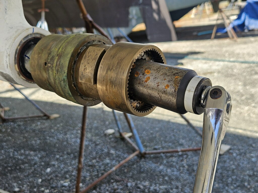
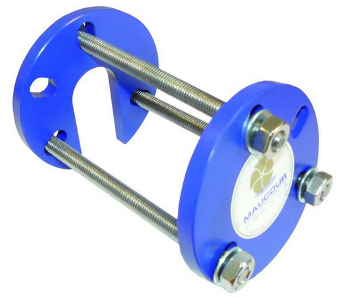
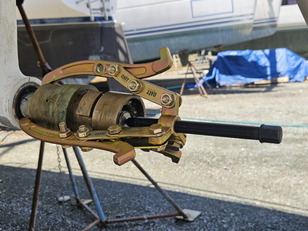
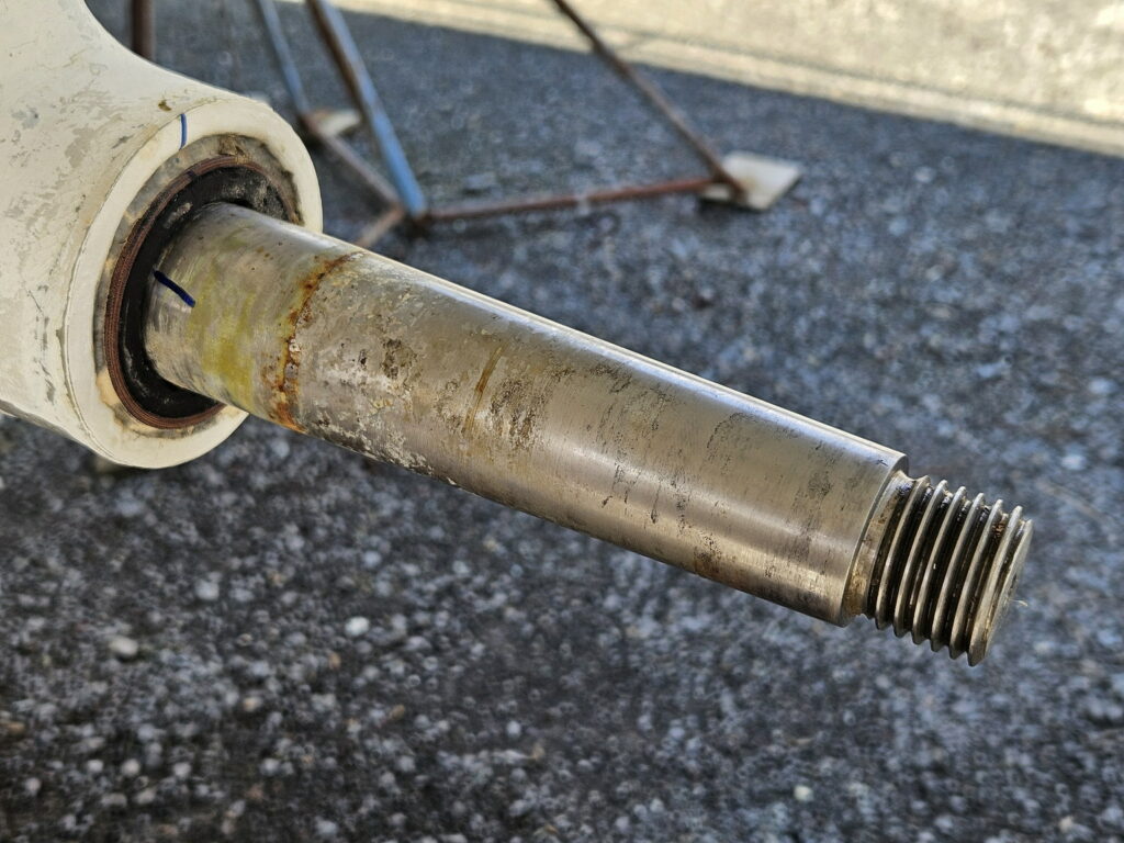
What is left is to pull the hub out as it seems tight on the shaft cone. The manual shows a small puller and a picture that does not really correspond to what the actual hub looks like. Seaview in Europe sent a picture of a proper puller I would need. The arms extent should be at least 6 1/2 inches. Such puller normally costs around $200. I found a different contraption on Amazon for $38. Maybe not convenient to use on a regular basis, but ok for using a one time job. In the end, the hub came off very easily and I think I could have saved the puller and gently tapped with a plastic mallet (although I don’t like the idea of imposing any shock on the coupler at the other end of the shaft).
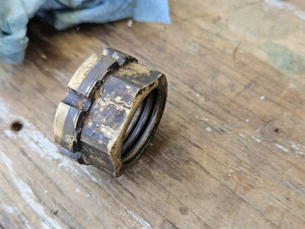
With the hub off the shaft, I contemplated disassembling it further for cleaning. PYI did not recommend doing so, which somewhat makes sense as the internal mechanism for pitch adjustment with the ring on a loaded spring must be quite complex. Instead, I just soaked it and moved the ring through its full range several times as this seemed to squeeze more dirty grease out.
Reassembling and greasing
With the parts clean, one can now reassemble. It is just a reverse order, and the manual as very clear instructions on how to assemble the propeller.
I put grease on and inside the parts during the reassembly.
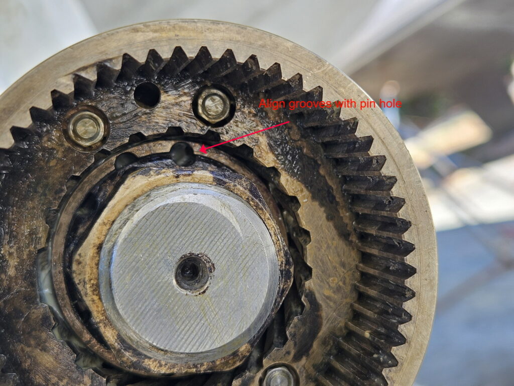
There are a few items to pay attention to and get right. The first one is to tighten the nut as align its groves with the pin holes on hub. And then put the lock pins in correctly as to not interfere with the insertion of the cone gear. The manual has good instructions/illustration on this topic.
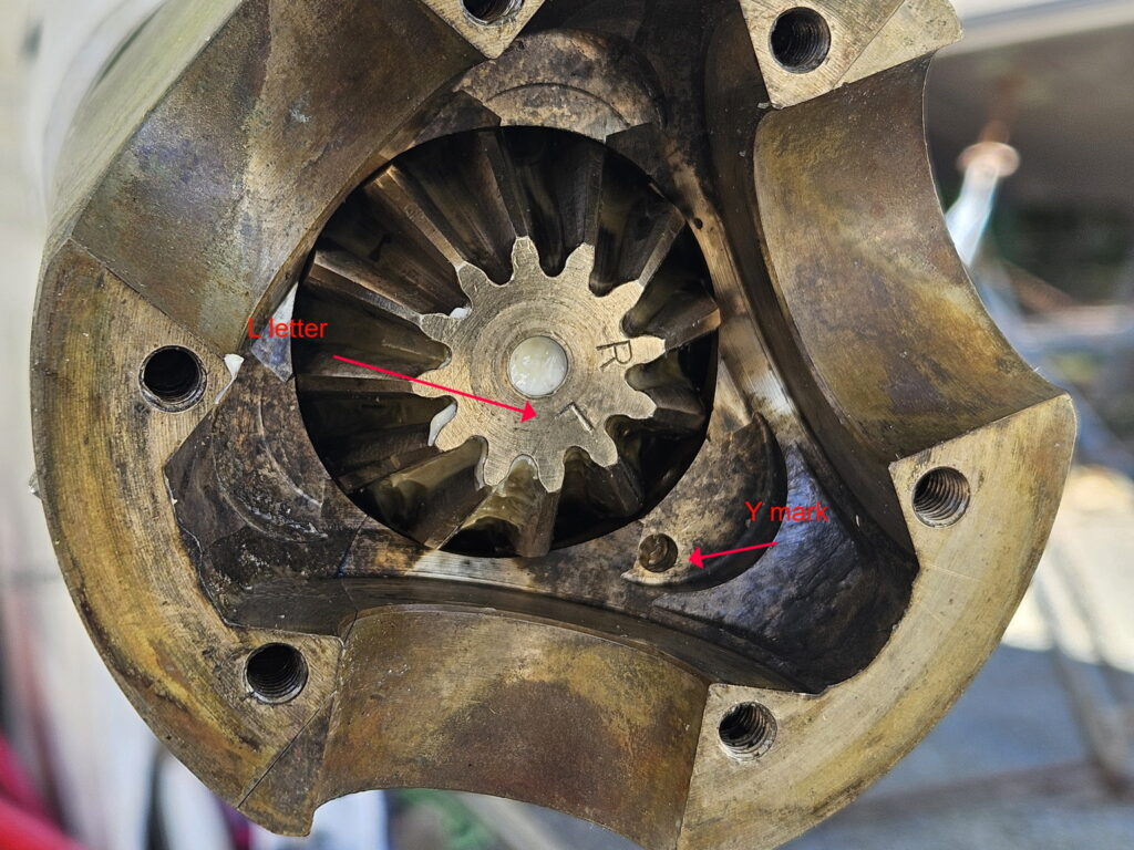
Next is to insert the cone gear and align the “L” letter with the hole (called the “Y” mark in the manual) on the spinner. For a right rotation, it would be the “R” letter of course, but we are a left rotation.
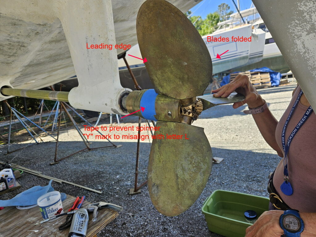
The spinner must now not move anymore as to maintain that alignment when putting the blades and spacer in place. We used tape to lock it in place with the alignment.
The last, but most important thing is that the blades are numbered 1, 2, and 3. They are marked on the spinner, on the spacer, on the blades themselves, and on the end cap. All those four parts must have their numbers aligned or rather, correspond perfectly. We had them correspond on all first three parts, but when it was time to put the end cap on, the numbers did not correspond. We had to remove the blades/spacer, turn the spacer around (upside down on the table) and remount.
Last thing was to add grease and mount the spacer. Very last thing was to add the cotter pins to lock the bolts.